Logan Buchalter
WaveWise
Generate Product Development, Northeastern University
Relevant Skills: pneumatic system design, ingress protection design, drivetrain construction, team coordination
Objective
WaveWise aims to create a self-sustained buoy/ submersible system to measure water parameters and raise/lower kelp-growing lines accordingly. My team was tasked with redesigning the system to implement a pneumatic lift mechanism and strengthen the buoy.
Variables / Constraints
My team had to work within a designated budget of $2500, and had a timeframe of approximately 3 months. The primary lift mechanism had to be pneumatic and incorporate a winch backup. The power consumption must be managed via onboard solar panels.
Role
As Lead Mechanical Engineer, I divided my team of 4 engineers between the lift, buoy, and submersible subsystems based on each teammate's preferences and skills. I performed buoyancy calculations to validate pneumatic designs, helped with part selection, provided mentorship on topics such as 3D printing, waterproofing, and drivetrain/winch design. I also designed 3D printed sealing caps to protect the submersible electronics.
Design Process
[1] Before the project began, I met with the project lead and lead electrical engineer to develop a timeline. Based on client communications, we identified key deliverables and developed a Gantt chart to guide our progress. I performed pneumatic/buoyancy calculations to determine an appropriate scale for our submersible.

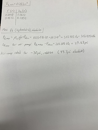
Sample pneumatic calculations
[2] Once an adequate scale was determined, I worked with my teammates to select an air chamber, solenoid valve, and air compressor to operate the pneumatic system. Concurrently, I oversaw buoy flotation calculations and float selections. I also helped my engineers construct preliminary CAD models for each subsystem.

Sketch of pneumatic and winch system

Order of operations for raising/lowering kelp and submersible

Prototype CAD design for buoy enclosure
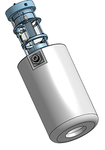
[3] I continued to work with my engineers to source parts and finalize the CAD, which necessitated several important decisions. We decided to house the submersible PCB in a watertight capsule above the air chamber, and I worked with another engineer to develop a 3D printed cap with o-ring slots to seal this capsule. The cap had an attachment point for the valve, and air/cable inlets were to be sealed with marine epoxy. The buoy itself was to be enclosed by acrylic laser-cut panels in order to protect the winch motor, air compressor, buoy PCB, and other vital electronics.
.png)
.png)
Submersible capsule (top) and air chamber (bottom)

Airtight top capsule with sensor array, suspended PCB
.png)
Buoy with solar panels, acrylic, and floatation devices attached

Closeup of cap with internal valve bracket, air tube/cable passthroughs, and o-ring slots
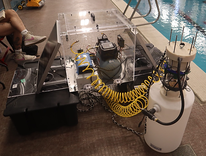
[4] As parts arrived, I machined the winch system gears to include slots and set screws. Assembly was completed, and the pneumatic system and seals were validated via water testing. I designed and implemented a ratchet and pawl subsystem to control winch direction via a servo motor.
Underwater air pneumatic system testing

Ratchet system (springs and rope attached during assembly)
Solution
By the end of the allotted timeframe, the team successfully developed a pneumatic lift system and a more robust buoy enclosure/flotation device. Provided calculations will allow the client to upscale the lift system for use in deeper ocean water under the load of kelp lines.

Submersible with air lines connected, hooks for kelp line attachment

IP enclosure for buoy PCB
.png)
Final project