Logan Buchalter
Faraday Cage
Emphysys Inc.
Relevant Skills: metal machining, EMI/EMC shielding, creepage/clearance
Objective
Draft and create a Faraday cage for a medical testing device with high voltage passthroughs
Variables / Constraints
During EMI/EMC testing, the testing device emitted interference on the order of MHz. The Faraday cage needed to prevent these wavelengths from reaching the medical device being tested. In addition, passthroughs for high voltage that prevented conduction to the cage itself were necessary.
Design Process
[1] To begin this project, I calculated the maximum allowable opening size in the cage. This value guided construction of the CAD assembly. The machine shop had perforated aluminum and 80/20 extrusions on hand, so I opted to build the frame of the cage from these materials. The holes in the perforations were far smaller than the maximum opening size.

SolidWorks model of Faraday cage
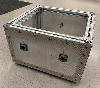
Perforated aluminum frame
[2] Next, I designed the high voltage passthroughs. Modeling around a high voltage wire jack, I developed a nonconductive resin piece to act as a buffer between the conductive cage frame and cable. In designing this, I had to consider both creepage and clearance. For the USB connection, I opted for a shielded bulkhead connector. All mounting holes had to be smaller than the maximum opening size.

Creepage/clearance prevention passthrough installed in cage, wire jack in center

Isometric view of passthrough
Solution
Before testing, I covered the exterior of the cage in aluminum tape as an added layer of shielding. I then added an EMI gasket to the lid, and the cage was used in testing. During testing, the target wavelengths were successfully contained within the Faraday cage, leading to a passing emissions score.
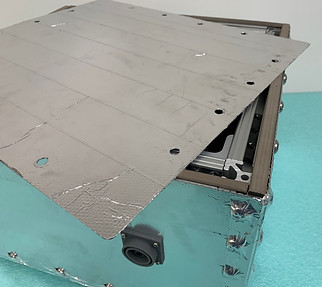
Closeup of lid highlighting aluminum tape and EMI gasket
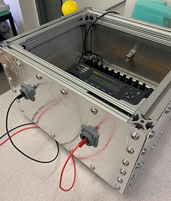
Testing device positioned in cage, high voltage cables connected