Logan Buchalter
Fluid Heating, Filtering, and Distribution System
ASMPT NEXX Inc.
Relevant Skills: complex SolidWorks modeling, fluid transfer systems, pneumatics, plastics, new product development
Objective
Design a system capable of delivering a fixed amount of filtered water at a given temperature to the drying module of a semiconductor plating machine
Variables / Constraints
Since the fluid module would be located below the main wafer plating floor, it needed to fit within a specific footprint. The delivered water had to be deionized, filtered, and at 60°C. To prevent stagnation, the water had to be constantly cycling throughout the heater and filter, and the water tank needed to hold enough water for at least 10 drying cycles.
Design Process
[1] To begin, I was given the specifications for the chosen pump, heater, and filter. Before developing an assembly, I researched fluid fittings and water-resistant plastics for the interior of the system. I decided to use flare fittings for water transport, pneumatic valves to divert water flow, and high-density polyethylene for interior brackets and panels. HDPE was chosen due to its chemical resistance and waterproof properties. One-touch fittings were selected to connect the compressed air lines to each valve.

Example of flare fitting used in the system for fluid transport
[2] To establish a footprint, I built a frame from 80/20 in SolidWorks. After developing an HDPE drip tray to hold the components, I sketched the general layout of the system. Since the system needed to resist tipping, I eventually decided to place the heavy water tank in the center of the module, with the water pipelines routing around. The water tank required a custom HDPE lid to accommodate sensors and water inlet/outlets. Custom draw latch mounts and gasketing mated the lid to the tank. To maintain water flow, I positioned the inlets to the tank such that there was constant circular flow within the tank.

80/20 frame similar to the fluid module

HDPE tank with outlet similar to tank used in module
[3] With the fluid circulation, refill, and exit paths installed in the assembly, I moved on to safety features and sensors. To monitor water level in the tank for refills, I added an EchoPod on top of the tank to measure water level via ultrasonic sensing, and I performed calculations and communicated with a vendor to produce a custom dual buoy switch to detect low/high water levels in the tank. For accurate water temperature, two resistance temperature detectors (RTDs) were suspended in the tank as well. To prevent the inline heater from running without water and creating a fire hazard, a flow sensor was placed directly upstream of the heater inlet. In the spill tray below the system, I added two water sensors. If either sensor was tripped, the system would assume a leak and stop immediately.
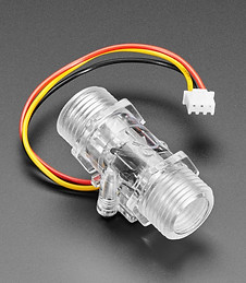
Flow sensor

EchoPod water level sensor

Resistance temperature detectors (RTDs)
[4] The last step in the assembly was to integrate the electronics. The electrical team provided a model for the electrical box and components, which I mounted on the side of the module. To prevent heat loss and mitigate shock risk, I shifted the components in the box to allow for a custom mounting bracket. This aluminum bracket housed all of the necessary cable bulkheads and allowed wires to pass directly from the enclosure to the electrical box.

Cable bulkhead panel similar to custom cable passthrough
Solution
By the end of my co-op at ASMPT NEXX, the assembly was nearly complete. After resizing the module to accommodate a larger heater, the assembly was comprised of nearly 2000 components. Throughout the process, I initiated and participated in several design reviews, which ensured that the finished project incorporated all of the required features and heeded all constraints.