Logan Buchalter
Fufu Pot
Generate Product Development, Northeastern University
Relevant Skills: project management, team leadership, sheet metal fabrication, metal machining, material selection
Objective
Fufu Pot is an appliance that automates the laborious process of making fufu, a staple in traditional West African cuisines. My team and I were tasked with creating a device to heat and mix fufu powder with the press of a button.
Role
Variables / Constraints
My team had to work within a designated budget of $1500, and had a timeframe of approximately 3 months. The device had to incorporate heating a high-torque mixing, all while fitting within the weight and footprint of other mixing appliances on the market.
As Lead Mechanical Engineer, I assigned my mechanical team of 4 to different subsystems of the project based on skills, goals, and interest. Throughout the semester, I mentored my teammates on topics such as material selection, 3D printing, gearing, tolerancing, and best CAD practices. I also consulted with the electrical lead to synthesize each subsystem.
Design Process
[1] Before the team began working, I met with the project lead and lead electrical engineer to develop a timeline. Through client communications, we identified key deliverables and developed a Gantt chart to guide our progress. I developed a detailed bill of materials and budget tracking document, and set up our shared Onshape CAD folder.
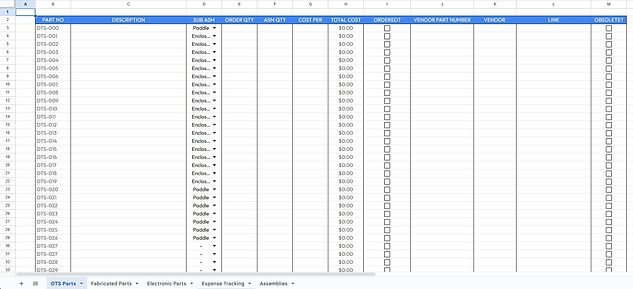
Excerpt from BOM and expense document
[2] After extensive test cooking sessions, we opted to use the modified planetary gear system of a stand mixer to create a motion capable of mixing the fufu flour. From our experimentation, I was able to select a brushless DC motor that provided sufficient torque for the mixing system. Another engineer and I researched gear reduction methods to couple the motor to the planetary system, ultimately deciding to use a 30:1 worm and worm gear. At the same time, I supported the frame design, which was constructed primarily from 80/20.
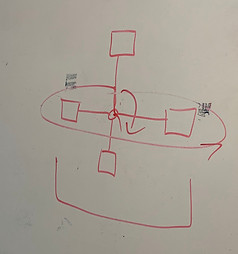
Rough sketch; overhead "pinwheel" mixing

80/20 frame for system

Rough sketch; planetary system

Rough sketch; Dual gear, quad paddle mixing system

Planetary mixing system from a stand mixer
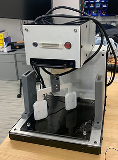
[3] With the gears selected, I worked with the other engineers to secure the drivetrain in the top compartment of the system. On the worm and worm gear, I machined tapped holes for set screws, while I turned down the diameter of the planetary shaft using a lathe. I designed a horizontal shaft stabilizer and worked on a sheet metal motor bracket to prevent misalignment over time due to vibration. Due to machining capabilities, I designed non-structural panels to be laser cut from acrylic, while panels that bore a load or were subject to steam / heat were chosen as aluminum. Since inductive heating was used in the base of the machine, non-magnetic paneling was necessary to prevent the system from heating up.

Gearbox with 3D printed shaft stabilizers and metal motor bracket
Motor system testing

Sheet metal motor bracket

CAD of drivetrain assembly

Horizontal shaft stabilizer
[4] Once the drivetrain was successfully tested, wires were routed from the inductor and motor to their respective controllers and the power supply. After organizing the cables, I installed the acrylic and sheet metal panels to close the assembly. Gasketing was placed between the frame and the panels to prevent steam from entering the system. I custom-ordered a plate of ceramic glass to serve as an induction stovetop.

Motor compartment with motor driver, cables routed and managed
Solution
By the provided deadline, the system was fully enclosed and provided reliable motor operation at the push of a button. The system was approximately the size and weight of a stand mixer as well.

Final product at the Generate Product Showcase
Final product

Operation of final product at Product Showcase